
eo_logo
 
Product added to cart
Filter

Optical Filters

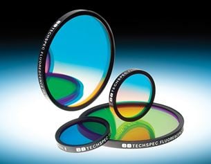
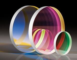
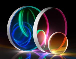
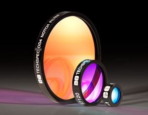
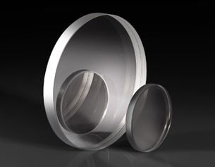
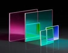
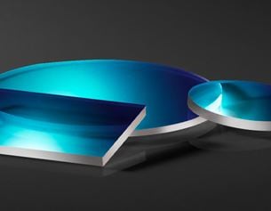
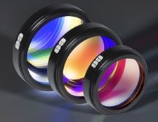
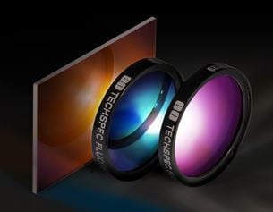
Optical Filters are used to selectively transmit or reject a wavelength or range of wavelengths. Optical Filters are used in applications such as fluorescence microscopy, spectroscopy, clinical chemistry, or machine vision inspection. Optical Filters are ideal for life science, imaging, industrial, or defense industries. Edmund Optics offers a variety of Optical Filters for many applications, including bandpass interference, notch, edge, dichroic, color substrate, or ND. Edmund Optics also offers highly durable hard coatings for applications that require high optical densities with maximum performance.

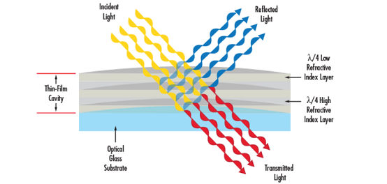
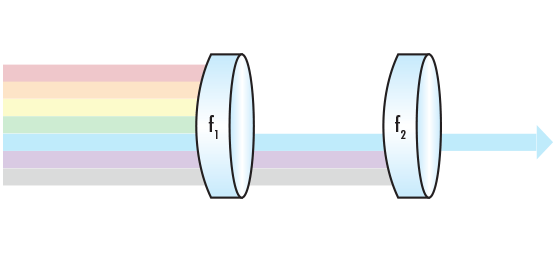
Bandpass Interference Filters are designed to transmit a portion of the spectrum, while rejecting all other wavelengths. Notch Filters reject a portion of the spectrum, while transmitting all other wavelengths. Edge or Dichroic Filters transmit wavelengths that are either greater than the cut-on or shorter than the cut-off wavelengths. Color Substrate Filters utilize the material’s inherent adsorption and transmission properties, while ND Filters evenly reduce transmission across a portion of the spectrum.

Note: Filter curves are available on all product family and stock level pages.

Understanding Optical Filter Types

Compare common optical filters by how they transmit, block, or reflect different wavelengths.

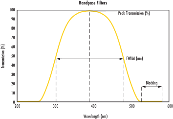
Bandpass spectral curve showing a transmission band with blocking on both sides
A defined wavelength band is transmitted while wavelengths on either side are blocked.

Bandpass Filters

Transmit a defined range of wavelengths while blocking shorter and longer wavelengths.

How to read the curve: Look for a transmission peak bounded by blocking regions at shorter and longer wavelengths.

Key Terms

Center Wavelength
The wavelength at the center of the passband, commonly abbreviated as CWL.
FWHM
The width of the passband measured at 50% of its maximum transmission.
Peak Transmission
The maximum percentage of incident light transmitted by the filter.

Related type: Multi-bandpass filters provide two or more transmission bands in one filter.
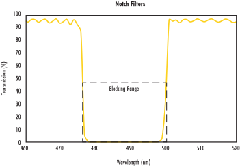
Notch filter spectral curve showing a blocked band between two transmitting regions
A defined wavelength band is blocked while wavelengths on either side are transmitted.

Notch Filters

Block a defined range of wavelengths while transmitting wavelengths on either side.

How to read the curve: Look for a narrow drop in transmission surrounded by transmitting regions.

Key Terms

Stopband
The wavelength range blocked by the filter, often centered on a laser wavelength.
Blocking Method
Light may be blocked through absorption or reflection.
Other Names
Notch filters may also be called band-stop or band-reject filters.
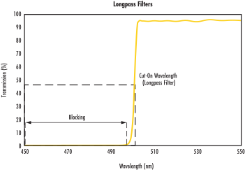
Longpass spectral curve showing shorter wavelengths blocked and longer wavelengths transmitted
Shorter wavelengths are blocked and longer wavelengths are transmitted.

Longpass Filters

Transmit wavelengths longer than a specified cut-on wavelength and block shorter wavelengths.

How to read the curve: Transmission is low on the short-wavelength side and rises as the curve crosses the cut-on wavelength.

Key Terms

Cut-On Wavelength
The wavelength that defines the transition from blocking to transmission.
Edge Steepness
The width of the transition between the blocking and transmitting regions.
Edge Measurement
Edmund Optics measures the transition from 10% to 80% transmission.

Example: A 1% edge slope at 500 nm corresponds to a 5 nm transition width.

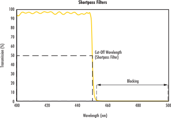
Shortpass spectral curve showing shorter wavelengths transmitted and longer wavelengths blocked
Shorter wavelengths are transmitted and longer wavelengths are blocked.

Shortpass Filters

Transmit wavelengths shorter than a specified cut-off wavelength and block longer wavelengths.

How to read the curve: Transmission is high on the short-wavelength side and falls as the curve crosses the cut-off wavelength.

Key Terms

Cut-Off Wavelength
The wavelength that defines the transition from transmission to blocking.
Edge Steepness
The width of the transition between the transmitting and blocking regions.
Edge Measurement
Edmund Optics measures the transition from 10% to 80% transmission.

Example: A 1% edge slope at 500 nm corresponds to a 5 nm transition width.

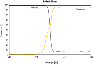
Dichroic filter spectral curve showing transmitted and reflected wavelength regions
One wavelength region is transmitted while another is reflected.

Dichroic Filters

Separate a broad spectral range into transmitted and reflected wavelength bands.

How to read the curve: One spectral region is transmitted while the complementary region is reflected.

Key Terms

Angle of Incidence
Dichroic filters are frequently designed for a 45° angle of incidence.
Spectral Behavior
Designs may provide longpass or shortpass transmission.
Common Application
Separating excitation and emission wavelengths in fluorescence imaging systems.

Also called: Dichroic mirrors or dichroic beamsplitters.

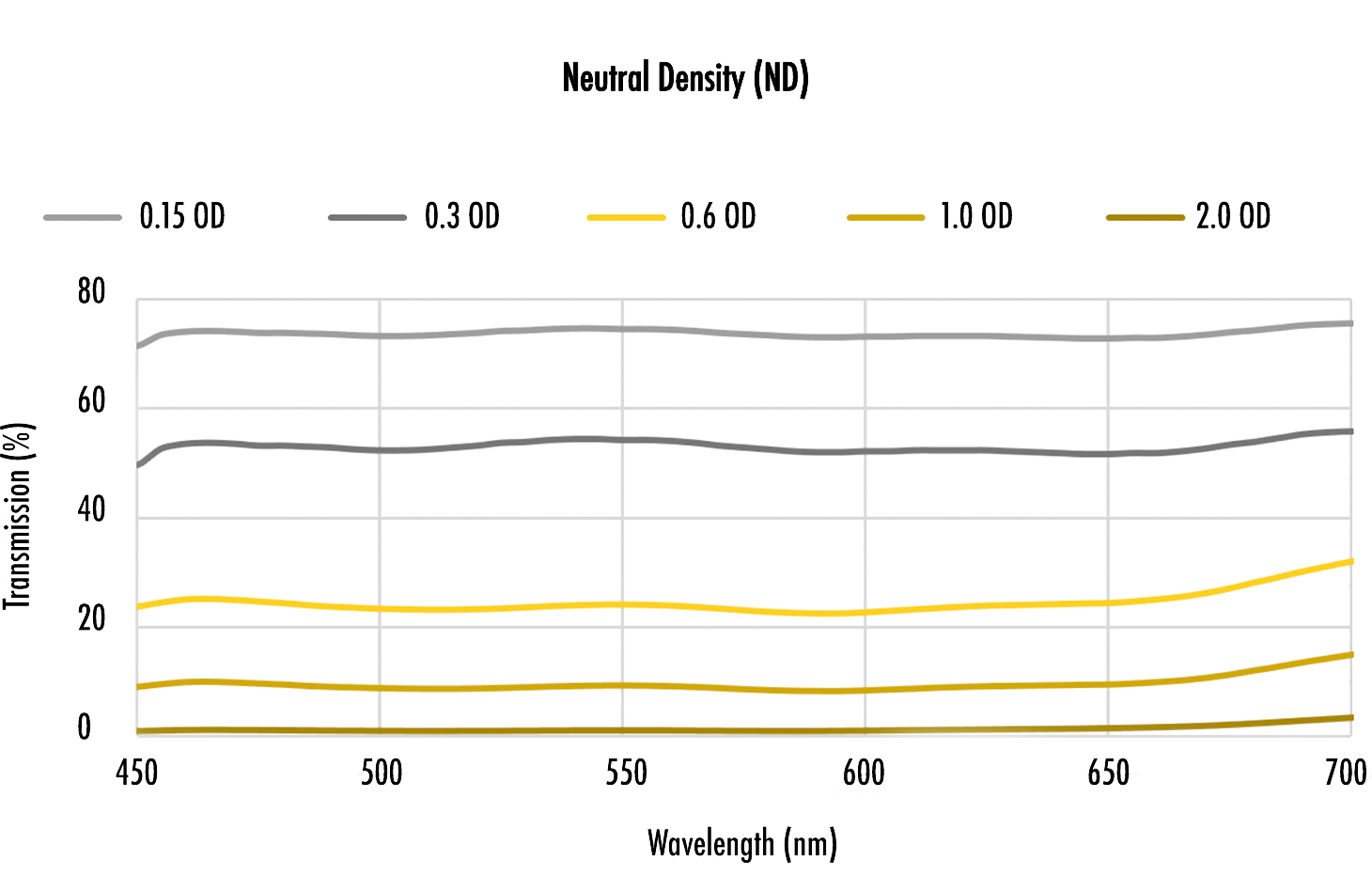
Neutral density filter curves showing lower transmission at higher optical densities
Transmission decreases as optical density increases.

Neutral Density Filters

Reduce light transmission by a specified amount across a wavelength range.

Key Terms

Optical Density
A logarithmic measure of attenuation, commonly abbreviated as OD.
Transmission
Each whole-number increase in OD reduces transmission by a factor of 10.
Filter Types
Absorptive filters absorb light within the glass, while reflective filters use a coating to reflect light.

Example: OD 1 transmits 10% of incident light, while OD 2 transmits 1%.

 
Sales & Expert Advice
 
or view regional numbers
Easy-to-Use
QUOTE TOOL
enter stock numbers to begin