


Optical Filters
Filter Terminology | Fabrication Techniques | Selection Guide| Application Examples
Introduction to Optical Filters
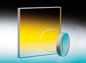
An optical filter selectively transmits one portion of the optical spectrum, while rejecting other portions. Commonly used in microscopy, spectroscopy, chemical analysis, and machine vision, Edmund Optics’ optical filters are available in a variety of filter types and precision levels. This application note provides a description of the different technologies used to create Edmund Optics filters, definitions of some key specifications, and a description of the various types of filters available from Edmund Optics.
Key Optical Filter Terminology
While filters share many of the same specifications with other optical components, there are a number of specifications unique to filters that should be understood in order to effectively understand and determine which filter is best for your application.
Central Wavelength
Center Wavelength (CWL), used in defining bandpass filters, describes the midpoint of spectral bandwidth over which the filter transmits. Traditional Coated Optical Filters tend to achieve a maximum transmission near the center wavelength, whereas Hard Coated Optical Filters tend to have a fairly flat transmission profile over the spectral bandwidth.
Bandwidth
Bandwidth is a wavelength range used to denote a specific part of the spectrum that passes incident energy through a filter. Bandwidth is also referred to as FWHM (Figure 1).

Figure 1: Illustration of Center Wavelength and Full Width at Half Maximum
Full Width-Half Maximum
Full Width-Half Maximum (FWHM) describes the spectral bandwidth over which a bandpass filter will transmit. The upper and lower limit of that bandwidth is defined at the wavelengths where the filter achieves 50% of the maximum transmission. For example, if the maximum transmission of the filter is 90%, the wavelengths at which the filter achieves 45% transmission will define the upper and lower limits of the FWHM. FWHM’s of 10nm or less are considered narrowband and often used for laser clean-up and chemical detection. FWHM’s of 25 – 50nm are often used in machine vision applications; FHWM’s of more than 50nm are considered broadband and typically used in fluorescence microscopy applications.
Blocking Range
Blocking Range is a wavelength interval used to denote a spectral region of energy that is attenuated by the filter (Figure 2). The degree of its blocking is typically specified in terms of optical density.
Figure 2: Illustration of Blocking Range
Slope
Slope is a specification often defined on edge filters, such as shortpass or longpass filters, to describe the bandwidth over which the filter transitions from high blocking to high transmission. Given as the percent of the cut-wavelength, slope can be specified from a variety of starting and end points. Edmund Optics typically specifies the slope as the distance from the 10% transmission point to the 80% transmission point. For example, a 500nm longpass filter with a 1% slope would be expected to transition from 10% transmission to 80% transmission over a 5nm (1% of 500nm) bandwidth.
Optical Density
Optical Density (OD) describes the amount of energy blocked or rejected by a filter. A high optical density value indicates low transmission, and low optical density indicates high transmission. Optical densities of 6 or greater are used for extreme blocking needs such as Raman spectroscopy or fluorescence microscopy. Optical densities of 3.0 – 4.0 are ideal for laser separation and clean-up, machine vision, and chemical detection, while optical densities of 2.0 or less are ideal for color sorting and separating spectral orders.

Figure 3: Illustration of Optical Density
Dichroic Filter
A Dichroic Filter is a type of filter used to transmit or reflect light, depending on the wavelength; light of a specific wavelength range is transmitted, while light of a different range is reflected or absorbed (Figure 4). Dichroic filters are commonly used for longpass and shortpass applications.

Figure 4: Illustration of a Dichroic Filter Coating
Cut-On Wavelength
Cut-On Wavelength is a term used to denote the wavelength at which the transmission increases to 50% throughput in a longpass filter. Cut-on wavelength is indicated by λcut-on in Figure 5.

Figure 5: Illustration of Cut-On Wavelength
Cut-Off Wavelength
Cut-Off Wavelength is a term used to denote the wavelength at which the transmission decreases to 50% throughput in a shortpass filter. Cut-off wavelength is indicated by λcut-off in Figure 6.

Figure 6: Illustration of Cut-Off Wavelength
Optical Filter Fabrication Techniques
In general, filters either absorb unwanted light through the addition of colored glasses or dyes, or reflect unwanted light through the addition of interference coatings. Most Edmund Optics filters operate on the principal of interference coatings, with coating designs and materials specially selected to achieve the desired transmission shape and performance. Hard Coated Optical Filters feature a single substrate with dense coatings and excellent optical performance. Designed to meet the adhesion, abrasion, temperature, and humidity requirements specified in MIL-C-48497A, they are ideal for precision requirements and OEM integration. Traditional Coated Optical Filters are typically a stack of absorbing materials, interference coatings, and metallic layers, laminated together to create a low-cost, efficient filter. The complexity of the assembly, however, limits both the optical performance and environmental stability of such filters. Nonetheless, traditional coated filters are ideal for laboratory equipment and analytical instrumentation. Colored Glass Filters and other absorbing filters like Plastic Filters and Wratten Filters, introduce elements, compounds, dyes, or other colorants to a base substrate to manipulate the filter’s spectral properties. The resulting filters are relatively inexpensive, but have less desirable optical properties than similar coated filters. Absorptive filters are typically integrated into illumination and sensing applications.
Absorptive and Dichroic Filters
The wide range of optical filters can be broken into two main categories: absorptive and dichroic. The difference between the two does not lie in what they filter, but how they filter. In an absorptive filter, light is blocked based on the absorption properties of the glass substrate used. In other words, light that is blocked does not reflect off the filter; rather, it is absorbed and contained within the filter. In applications where noise in a system from unwanted light is an issue, an absorptive filter is ideal. Absorptive filters also have the added bonus of not being very angle sensitive; light can be incident upon the filter from a wide range of angles and the filter will maintain its transmission and absorption properties.
Conversely, a dichroic filter works by reflecting unwanted wavelengths, while transmitting the desired portion of the spectrum. In some applications, this is a desirable effect because light can be separated by wavelength into two sources. This is achieved by adding a layer, or multiple layers, of material of varying indexes of refraction to exploit the interference nature of light waves. In interference filters, light traveling from a lower index material will reflect off a higher index material; only light of a certain angle and wavelength will constructively interfere with the incoming beam and pass through the material, while all other light will destructively interfere and reflect off the material (Figure 7). For additional information on interference, view Optics 101: Level 1 Theoretical Foundations.

Figure 7: Deposition of Multiple Layers of alternating High and Low Index Materials onto a Glass Substrate
Unlike absorptive filters, dichroic filters are extremely angle sensitive. When used for any angle(s) outside of their intended design, dichroic filters cannot meet the transmission and wavelength specifications originally indicated. As a rule of thumb, increasing the angle of incidence through a dichroic filter will shift it towards shorter wavelengths (i.e. towards bluer wavelengths); and decreasing the angle will shift it towards longer wavelengths (i.e. towards redder wavelengths).
Exploring Dichroic Bandpass Filters
Bandpass filters are used in a wide range of industries and can be either dichroic or color substrate. Dichroic bandpass filters are manufactured by two different techniques: traditional and hard sputtered, or hard coated. Both techniques achieve their unique transmission and reflection properties by a deposition of numerous layers of alternating high and low index of fraction materials onto glass substrates. In fact, depending upon the application, there can be more than 100 layers of material deposited per face of a given substrate.
The difference between traditional-coated filters and hard-sputtered filters is the number of substrate layers. In traditional-coated bandpass filters, layers of varying index materials are deposited onto multiple substrates which are then sandwiched together. For example, imagine the illustration in Figure 7 repeated up to and even more than 100 times. This technique leads to a thick filter with reduced transmission. This reduction in transmission is caused by incident light traveling through and being absorbed and/or reflected by numerous substrate layers. Conversely, in hard-sputtered bandpass filters, materials of varying indices are deposited onto only a single substrate (Figure 8). This technique leads to thin filters with high transmission. For additional information on fabrication techniques, view An Introduction to Optical Coatings. View the Benefits of Hard Coatings to help you select the correct filter for your application.

Figure 8: Traditional Filter (Left) and Hard-Sputtered Filter (Right)
Types of Optical Filters
To aid in understanding the similarities and differences between the large variety of optical filters available today, consider ten of the most popular types. The following selection guide contains a brief description, as well as sample product images and performance curves for easy comparison.
| Optical Filter Selection Guide | |
|---|---|
| Sample Image | Optical Filter Type – Sample Curve |
 |
Bandpass Filters [View Performance Curve] Bandpass filters have extremely narrow band (<2nm to 10nm) or broadband (50nm and 80nm) transmittance across the substrate. They are particularly angle sensitive, so care should be taken when mounting and placing them within an optical setup. Hard sputtered filters should be chosen to maximize the transmission of selected wavelengths. |
 |
Longpass Filters [View Performance Curve] Longpass filters transmit all wavelengths longer than the specified cut on wavelength. Longpass filters include cold mirrors, colored glass filters, and Thermoset ADC (optical cast plastic) filters. |
 |
Shortpass Filters [View Performance Curve] Shortpass filters transmit all wavelengths shorter than the specified cut off wavelength. Shortpass filters include IR cutoff filters, hot mirrors, and heat absorbing glass. |
 |
Heat Absorbing Glasses [View Performance Curve] Heat absorbing glasses will transmit visible light and absorb infrared radiation. The absorbed energy is then dissipated as heat into the air around the glass. Forced air cooling is typically recommended to remove the excess heat. Heat absorbing glass can also be used as shortpass filters. |
 |
Cold Mirrors [View Performance Curve] Cold mirrors are specific types of dichroic filters designed to have high reflectivity in the visible spectrum while maintaining high transmission in the infrared. Cold mirrors are designed for use in any application where heat build-up can cause damage or adverse effects. |
 |
Hot Mirrors[View Performance Curve] Hot mirrors are specific types of dichroic filters designed to have high reflectivity in the infrared spectrum and high transmission in the visible. Hot mirrors are used primarily in projection and illumination systems. |
 |
Notch Filters [View Performance Curve] Notch filters are designed to block a pre-selected bandwidth while transmitting all other wavelengths within the design range of the filter. Notch filters are used to remove a single laser wavelength, or narrow band, from an optical system. |
 |
Color Substrate Filters [View Performance Curve] Color substrate filters are manufactured from substrates with inherently different absorption and transmission properties across a specific spectral region. Color substrate filters are often used as longpass and bandpass filters. The boundary between transmission and blocking is less sharp compared to some coating based filters. |
 |
Dichroic Filters [View Performance Curve] Dichroic filters are coated with thin-films to achieve a desired transmission and reflection percentage across a given spectrum. They are often used as color filters (both additive and subtractive). Dichroic filters are slightly angle sensitive but are much more forgiving than interference filters. |
 |
Neutral Density (ND) Filters [View Performance Curve] Neutral density (ND) filters are designed to reduce transmission evenly across a portion of a certain spectrum, ultraviolet and visible, visible, or infrared. There are two types of ND filters: absorptive and reflective. The absorptive type absorbs light that is not transmitted through the filter, while the reflective type reflects it back toward the direction from which it was incident. Special care should be taken when using the former type in order to ensure that any reflected light does not interfere with the application setup. ND filters are often used to prevent blooming or overexposure of cameras and other detectors. |
APPLICATION EXAMPLES
Example 1: Color Match Imaging
Monochrome cameras cannot inherently differentiate different colors. However, the addition of a color filter greatly increases the contrast between objects. A good rule of thumb is that a given color filter will lighten objects of the same color, while darkening objects of opposing colors. Consider an example where two red and two green pills are imaged with a monochrome camera. Figures 9a - 9d show actual images of a sample under inspection and various images using color filters. It is clear to see that with no filter (Figure 9b), the monochrome camera cannot distinguish between red and green. It would be impossible to inspect these pills on a factory floor. On the other hand, when a red filter is used (Figure 9c), objects of its opposing color (i.e. the green pills) appear gray due to increased image contrast and can be easily discerned from the red pills. Conversely, when a green filter is used (Figure 9d), the red pills appear gray.

Figure 9a: Contrast Enhancement: Sample under Inspection

Figure 9b: Contrast Enhancement: No Filter

Figure 9c: Contrast Enhancement: Red Filter

Figure 9d: Contrast Enhancement: Green Filter
Example 2: Raman Spectroscopy
The results in a Raman spectroscopy application can be greatly improved by the use of a few select filters: laser line bandpass, rugate notch, or laser line longpass. To achieve the best results, use filters with bandwidths as narrow as 1.2nm and optical densities of OD 6.0. The laser line bandpass filter is placed in the optical path between the laser and the sample. This ensures that any external ambient light is blocked and only the laser line wavelength is passed. After the light is incident on the sample, it is shifted due to Raman scattering and contains many low intensity modes or signals. Therefore, it becomes very important to block the high intensity laser light through the use of a notch filter centered as close as possible to the laser wavelength. If Raman excitation modes occur very close to the laser line, then a laser line long pass filter can be used as an effective alternative. Figure 10 illustrates a typical Raman spectroscopy setup.

Figure 10: Raman Spectroscopy Setup
Optical filters are used in a multitude of applications beyond the two aforementioned: color match imaging and Raman spectroscopy. They are encountered in nearly every aspect of the optics, imaging, and photonics industries; understanding optical filters' fabrication techniques, key terminology, and the types of filters available today helps one select the best filter for any setup.


or view regional numbers
QUOTE TOOL
enter stock numbers to begin
Copyright 2023, Edmund Optics India Private Limited, #267, Greystone Building, Second Floor, 6th Cross Rd, Binnamangala, Stage 1, Indiranagar, Bengaluru, Karnataka, India 560038
California Consumer Privacy Acts (CCPA): Do Not Sell or Share My Personal Information
California Transparency in Supply Chains Act
The FUTURE Depends On Optics®