


How to Set Up an Optical Lab: Essential Equipment and Workflow
Authors: Yamila Borsch
Are you new to optics or already familiar with the basics but looking for a concise reference? This guide offers a compact and comprehensive overview of the key components for an optical laboratory setup. It covers the most important parameters, introduces common optical lab equipment, and outlines a practical workflow to help you build a stable, flexible, and precise optical lab system.
Optical Tables and Breadboards for Lab Setups
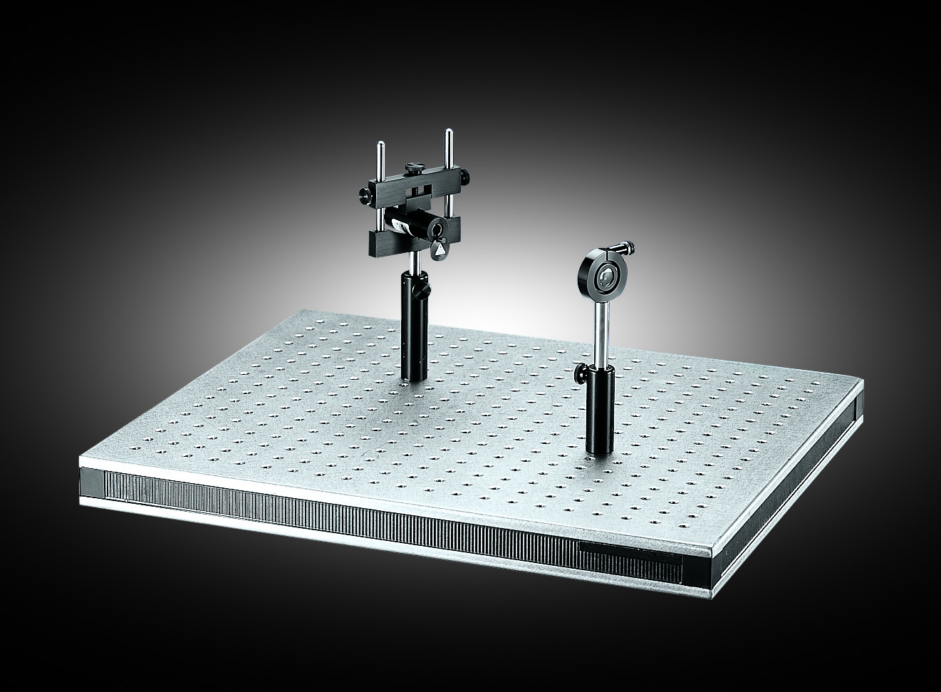
The optical table is the foundation of your setup. For sensitive experiments, it is strongly recommended to invest in a vibration-isolated optical table, as its damping system reduces environmental disturbances such as shocks and vibrations. This ensures a stable and reliable beam path. The surface of an optical table is covered with a regular hole pattern of threaded holes that allow secure mounting of optomechanical components. Breadboards (as shown in Figure 1), also called bench plates, are smaller plates with the same hole pattern. They can be placed on top of a table or any other surface, offering flexibility in positioning, modularity, or even transportability of your setup.
Best practice: Always ensure that all your optomechanics (screws, posts, holders, stages, etc.) match the chosen hole pattern. There are two hole pattern standards: English (imperial) with ¼”-20 threads on a 1” grid and metric with M6 threads (6 mm) on a 25 mm grid. Imperial and metric parts are not compatible.
Optical Posts and Post Holders
To fix your optical components on the table or breadboard, posts and post holders are used. Figure 2 gives an example on how such a setup looks like.
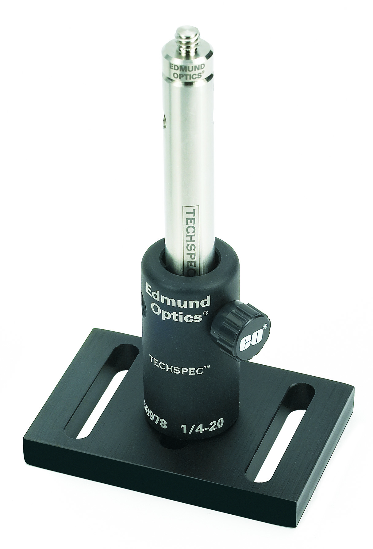
Posts are metal rods, usually threaded on both ends. They may also include male thread adapters. Their thread type (¼”-20 or M6) depends on whether you are working in an imperial or metric system. Posts come in various lengths, and can be combined with adapters to reach the desired optical height. They can be directly screwed into the table using a male thread or mounted in post holders. Post holders provide a stable fixture for posts and allow easier adjustment. A thumbscrew on the side locks the post into place. Post holders themselves are fixed to the table with screws matching the hole pattern. There are two types of post holders: Static post holders hold the post firmly using a three-point contact design. To make vertical adjustments, move the post in and out of the holder and secure it with the locking screw. Fine vertical adjustments are difficult. Adjustable (Z-adjust) post holders easily allow small vertical translations of the post while maintaining orientation. They can serve as a compact alternative to larger z-axis translation stages. Post collars can be used to lock the post height so the post can be rotated within the mount without re-adjusting the height. With the post collar, you can also quickly move mounts in and out of the optical path at the same height position.
Best practice: When choosing post lengths, consider the intended beam height carefully and aim for a consistent working height across your setup.
Linear Motion Components for Optical Labs: Rails and Carriers
When you need components to move linearly through the setup while staying aligned, rails and carriers such as those shown in Figure 3 are used.
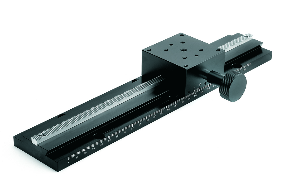
Carrier positioning is commonly performed manually, using manual translation stages. Rails are mounted on the table or breadboard, while carriers can move along them. A common example is the dovetail optical rail system, which keeps the carrier tightly aligned to the rail, avoiding tilt or wobble. Carriers typically include a locking screw for locking them in place. Some designs also feature knobs for fine translation along the rail. Rails and carriers are particularly useful when you need to reposition groups of optics without losing alignment (e.g., in interferometers or scanning systems). As with tables and breadboards, ensure metric/imperial compatibility.
Precision Stages for Optical Alignment: Translation, Rotation, Tilt
Precision stages provide fine alignment capabilities, allowing precise positioning for a wide range of optical applications. Depending on your setup requirements, you can choose from two adjustment options - manual translation stages and motorized translation stages. Manual stages typically use micrometer screws to enable fine linear positioning, while motorized stages can be connected to a computer’s USB or RS-232 port and are controlled via software.
Stages are divided into three main groups based on their direction of movement:
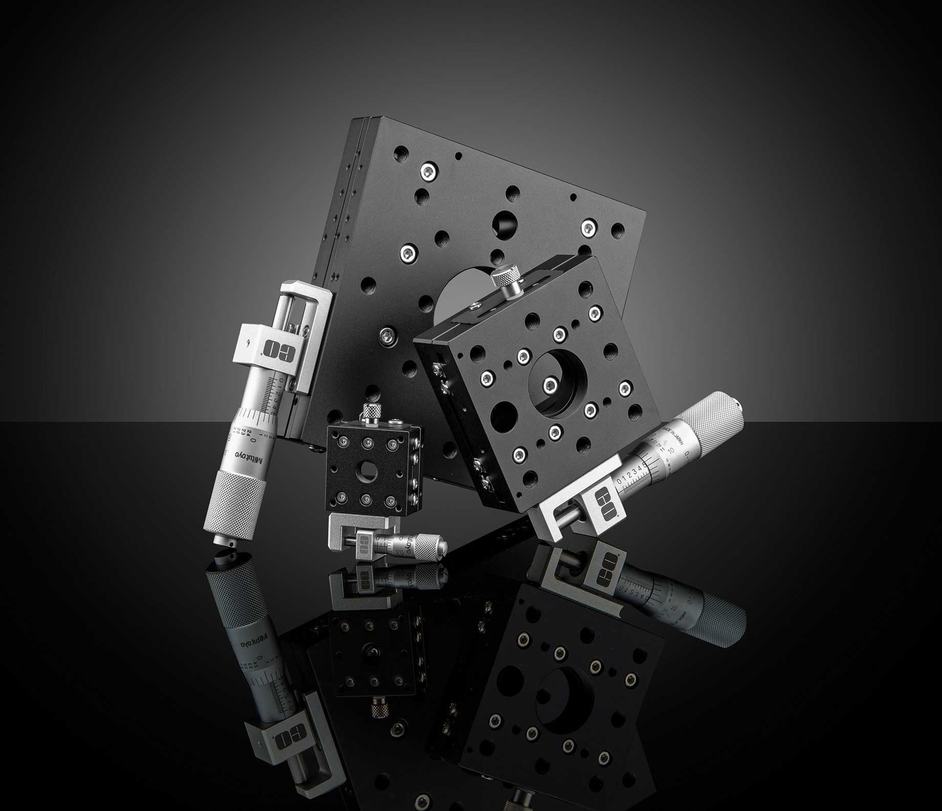
- Linear translation stages (like the ones shown in Figure 4) move components along one axis (x, y, or z), several stages can be combined into 2D or 3D stacks. Please refer to these videos for more information on the configuration of 2D translation stages and 3D translation stages.
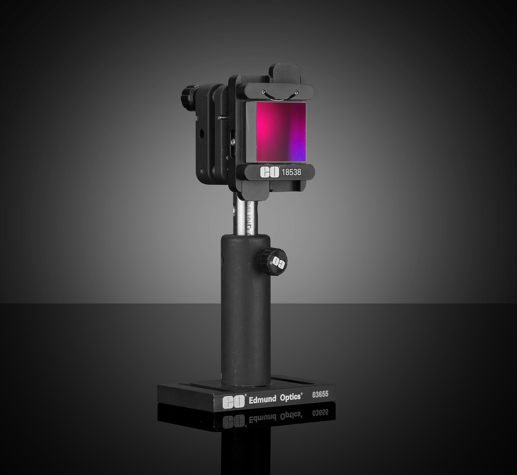
- Rotary stages allow controlled angular adjustment around a central axis. These stages are particularly useful for elements like polarizers, diffraction gratings, or crystals.
- Tilt stages, also known as goniometer stages, provide precise angular adjustment of optical components. By finely controlling tilt along one or two axes, they enable accurate alignment of mirrors, prisms, lenses, and other samples that require high angular precision in optical setups.
Precision stages can be mounted directly to the optical table, on top of breadboards, or on carriers for even greater flexibility. Combining them with posts, rails, and mounts allows you to create highly adaptable and precise systems. For further information, please watch our video explaining the key specifications for selecting manual translation stages.
Optical Mounts for Secure Positioning of Optics
So far, we have discussed how to position optical components in space. Equally important is how to mount optical components within the mechanical framework. Because optics come in many shapes and sizes, a wide variety of mounts exists. Fixed mounts are compact and rigid, suitable when alignment is not critical. The optic is fixed in place, and adjustments can only be made by moving the entire optomechanical assembly. Adjustable mounts are designed to hold optics of varying diameters. While they offer flexibility in what they can house, alignment still requires moving the whole mount. Kinematic mounts provide fine tip/tilt control via adjustment screws as seen in Figure 5. These are essential for precise beam steering, such as carefully aligning mirrors to guide a laser beam.
Dedicated holders exist for more specialized optics, such as beamsplitters, right-angle mirrors and off-axis mirrors. Always use the proper mount to avoid mechanical stress on the optics, more information can be found in our video highlighting important concepts for selecting optical component mounts.
Best practice: Handle all optics with care – use gloves or lens paper and avoid overtightening mounts.
Step-by-Step Optical Lab Installation Workflow
The following workflow offers a structured approach to building your setup. You may adapt it to personal preferences or experimental constraints.
- Place and level the optical table.
- Lay out base components such as breadboards or risers.
- Install rails and slides if flexible linear positioning is required.
- Add posts and post holders, then place primary mounts (e.g., mirror or lens holders) without optics to check spacing and fit.
- Insert optics once the mechanical structure is confirmed. Adjust post heights as needed.
- Perform rough alignment by adjusting tip/tilt on mounts.
- Lock fasteners to the recommended torque, ensuring nothing is loose or overtightened.
- Fine-tune alignment with micrometers, kinematic screws, and stages until the beam path is optimized.
Best practice: If you encounter mechanical resistance or instability, always test the component without optics installed first. Optics are delicate and expensive – integrate them only once you are confident the mechanics move smoothly.
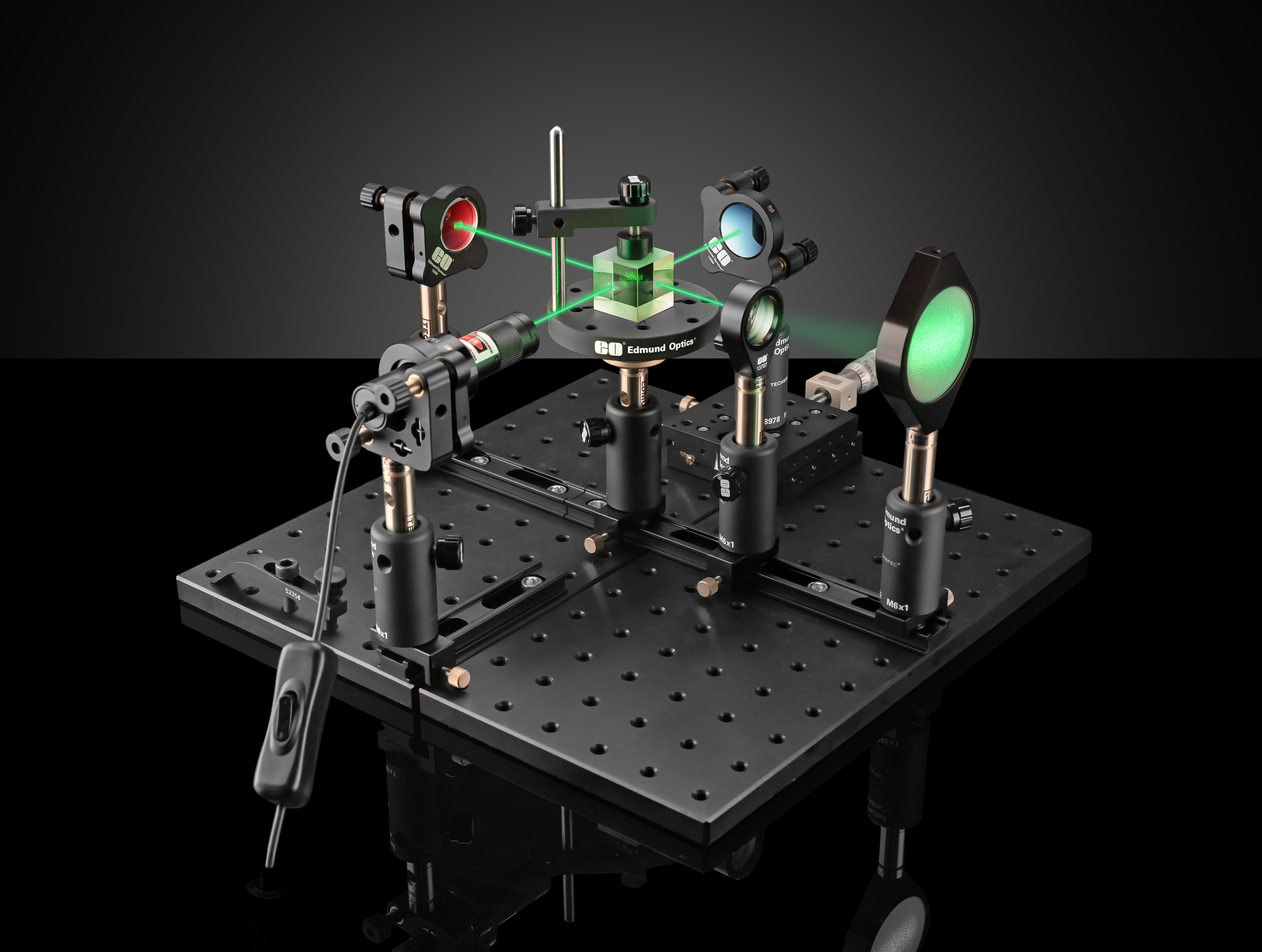
For more visual guidance please also have a look at Michelson Interferometer Lab Setup: Assembly and Alignment Guide, explaining each step of setting up a Michelson Interferometer like shown in Figure 6.


or view regional numbers
QUOTE TOOL
enter stock numbers to begin
Copyright 2023, Edmund Optics India Private Limited, #267, Greystone Building, Second Floor, 6th Cross Rd, Binnamangala, Stage 1, Indiranagar, Bengaluru, Karnataka, India 560038
California Consumer Privacy Acts (CCPA): Do Not Sell or Share My Personal Information
California Transparency in Supply Chains Act
The FUTURE Depends On Optics®