


Laser Resonator Modes
This is Section 4.1 of the Laser Optics Resource Guide.
The shape of a laser beam is determined by the resonator cavity, a laser optical mirror, in which the laser light is amplified in a gain medium. Laser resonators are typically formed by using highly reflective dielectric mirrors or a monolithic crystal that utilizes total internal reflection to keep light from escaping (Figure 1). Below is a list of common laser resonator geometries1:
- Plane parallel resonator: two flat mirrors separated by a distance equal to an integral multiple of one half of the lasing wavelength
- Concentric resonator: two spherical mirrors with the same radius of curvature and coincident centers of curvature
- Confocal resonator: two spherical mirrors with the same radius of curvature and coincident focal points
- Ring resonator: ring of more than two reflectors where the total closed loop path of the reflected light is equal to an integral multiple of one half of the lasing wavelength
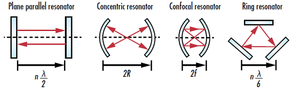
Figure 1: Four common types of laser resonator geometries where n is an integer value, λ is the lasing wavelength, R is the radius of curvature of a curved mirror, and f is the focal length of a curved mirror
Resonator cavities are “stable” if the reflected light stays inside the cavity, even as the number of reflections approaches infinity (Figure 2). In this instance, the only way for light to leave the cavity is through a partially reflective mirror. On the other hand, resonator cavities are considered “unstable” if the reflected light continuously diverges as the number of reflections approaches infinity. When this occurs, the beam size will grow until it is larger than the reflectors and then escape the system. Stable resonators are often used with lasers that have powers up to 2kW to achieve high gain and improve directionality. Unstable resonators are typically used with higher power lasers to reduce the chance of damaging the reflectors.1
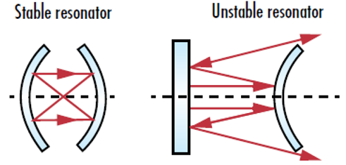
Figure 2: Stable laser resonators keep all reflected beams inside the confines of the cavity, while unstable resonators cause reflected light to spread out until it eventually escapes the cavity
The resonator cavity’s path length determines the longitudinal resonator modes, or electric field distributions which cause a standing wave in the cavity. The modes of a beam give it its shape. These modes maintain their amplitude profile and reproduce themselves after completing one closed loop path inside the resonator (aside from potentially losing some power due to loss in the cavity). In order for a resonant mode to occur, it must also experience a phase shift equal to an integer multiple of 2π over one closed loop path (Figure 3).
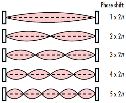
Figure 3: The phase shift of a complete loop in an optical resonator must be an integer multiple of 2π in order for a resonant mode to occur
The simplest type of laser resonator modes are Hermite-Gaussian modes, also known as transverse electromagnetic modes (TEMnm), in which the electric field profile can be approximated by the product of a Gaussian function with a Hermite polynomial2:
E_{nm} \! \left(x, y, z \right) = & \, E_0 \frac{w_0}{w \! \left( z \right)} \, \cdot \, H_{n} \left( \sqrt{2} \frac{x}{w \! \left( z \right)} \right) \\
& \cdot \exp{\left( -\frac{x^2}{w \! \left( z \right) ^2} \right)} \, \cdot \, H_m \left( \sqrt{2} \frac{y}{w \! \left( z \right)} \right) \cdot \exp{\left( -\frac{y^2}{w \! \left( z \right) ^2} \right)} \\
& \cdot \, \exp{\Bigg[ -i \left[ kz - \left( 1 + n + m \right) \cdot \tan^{-1}{\left( \frac{z}{z_R} \right)} + \frac{k \left( x^2 + y^2 \right)}{2 R \! \left( z \right) } \right] \Bigg]}
\end{align}
or
- E0 is the field maximum
- x and y are the axes that define a cross-section of the beam
- z is the axis of propagation
- w0 is the beam waist
- w(z) is the beam radius at a given z value
- Hn(x) and Hm(x) are the Hermite polynomial with the non-negative integer indices n and m
- k is the wavenumber (k=2π/λ)
- zR is the Rayleigh range
- R(z) is the radius of curvature of the wavefront
The integers n and m define the beam shape in the x and y directions, respectively. An ideal Gaussian beam is defined by the mode TEM00, which occurs when n and m are both equal to 0 (Figure 4). For more information on Gaussian beams, please refer to our Gaussian Beam Propagation application note. All other values of n and m produce more complicated resonator modes.3 In Figure 5, the cross-sectional geometries of the lowest order Hermite-Gaussian modes with n and m values ranging from 0 to 3 are shown.
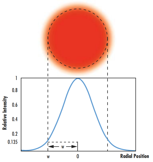
Figure 4: The Hermite-Gaussian resonator mode TEM00 corresponds to a perfect Gaussian beam
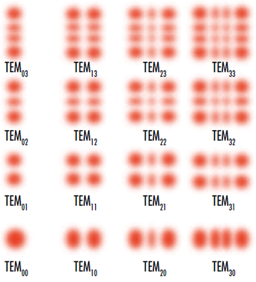
Figure 5: Cross-sections of the lowest-order Hermite-Gaussian resonator modes with n and m values ranging from 0 to 3
References
- “Section 2.6: Various Laser Resonators.” Advanced Manufacturing Laboratory, Columbia Engineering, www.aml.engineering.columbia.edu/ntm/level2/ch02/html/l2c02s06.html.
- Paschotta, Rüdiger. Encyclopedia of Laser Physics and Technology, RP Photonics, October 2017, www.rp-photonics.com/encyclopedia.html.
- Paschotta Rüdiger. Field Guide to Lasers. SPIE Press, 2008.
More Resources
- Gaussian Beam Propagation Application Note
- Beam Quality and Strehl Ratio Application Note
- Laser Optics Lab Video Series


or view regional numbers
QUOTE TOOL
enter stock numbers to begin
Copyright 2023, Edmund Optics India Private Limited, #267, Greystone Building, Second Floor, 6th Cross Rd, Binnamangala, Stage 1, Indiranagar, Bengaluru, Karnataka, India 560038
California Consumer Privacy Acts (CCPA): Do Not Sell or Share My Personal Information
California Transparency in Supply Chains Act
This content may include material that has been generated or modified using artificial intelligence (AI).
The FUTURE Depends On Optics®