


LIDT for Ultrafast Lasers
This is Section 14.8 of the Laser Optics Resource Guide.
Ultrafast lasers are pulsed, mode-locked lasers that emit pulses with extremely short durations (on the order of femtoseconds or picoseconds) and high peak powers. Due to the Fourier limit, or energy-time uncertainty, shorter temporal pulse lengths correspond to wide wavelength spectrum spreads, therefore ultrafast pulses have a broader wavelength bandwidth compared to longer pulses (Figure 1). Ultrafast lasers are beneficial for a wide variety of applications including high intensity physics, femtosecond materials processing, and laser spectroscopy.1
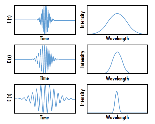
Figure 1: The wavelength bandwidth of ultrafast laser pulses is inversely related to the amount of time per pulse
In recent years, ultrafast laser-induced damage has been an active topic of research because the extremely short pulse duration of ultrafast lasers causes them to interact with optical coatings and components differently than other pulsed lasers. In general, the heating of thin film coatings after ultrafast laser exposure arises from non-equilibrium energy transport. Energy from incident photons is absorbed by the ground state electrons, which leads to an occupation of excited energy states within a few femtoseconds. These “hot” electrons then relax back to their ground state through picosecond-timescale phonon-electron and phonon-phonon scattering, allowing energy redistribution in the coating materials.2, 3 Phonon-electron scattering describes distortions in electron wave functions caused by lattice vibrations, and phonon-phonon scattering describes lattice vibrations inducing other vibrations in the lattice (Figure 2).
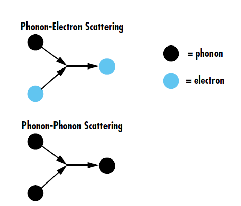
Figure 2: Phonon-electron scattering is the energy transfer between lattice vibrations and electrons, redirecting electrons inside the lattice. Phonon-phonon scattering, on the other hand, is the interaction of multiple lattice vibrations to make new phonons
Since the Fermi distribution of electrons is much faster than the electron lattice redistribution, the thin film can be described as a composition of two interacting subsystems: electrons and phonons.4 Knowing the temperature rise caused by ultrafast excitation is critical to understanding LIDT for ultrafast lasers. The hot carrier relaxation dynamics can be calculated theoretically and experimentally verified using ultrafast pump-probe spectroscopy, which measures the changes in the optical properties of the test optic as a function of time.5, 6
The electron and lattice thermal behavior under ultrafast laser excitation can be described by using a two temperature model assuming that the electron and lattice subsystems independently and spontaneously reach equilibrium. The coupled heat capacity equations are used to determine the theoretical temperature rise from ultrafast excitation and are given by:7
- Ce and Cl are the heat capacities for the electron and lattice subsystems
- Te and Tl are the electron and the lattice temperatures
- ke is the electron thermal conductivity
- S is a heating term introduced by the ultrafast laser pulse dependent on time (t) and space (z)
- G is the electron lattice coupling constant given by:
- me is the effective electron mass
- ne is the electron number density
- cs is the speed of sound in the bulk material described as the square root of the ratio of the bulk modulus over the density ρm
- τ(Te) is the electron relaxation time
Equation 1, Equation 2, and Equation 3 are used to provide Tl and Te as a function of time. Figure 3 shows the theoretical Tl and Te calculated for a 0.2 J/cm2 10fs ultrafast laser pulse centered at 800nm with a beam diameter of 120μm illuminating a 200nm thick gold nanofilm suspended on a copper substrate. The thickness of the gold nanofilm is much larger than the optical and electron penetration depth into the nanofilm.
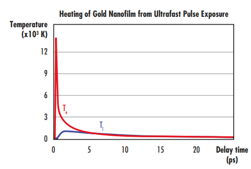
Figure 3: Time-dependent electron (red) and lattice (blue) temperature rise following the ultrafast laser excitation of a 0.2 J/cm2 10fs ultrafast laser pulse centered at 800nm. The heating of the gold nanofilm due to the rise of lattice temperature leads to initiation of laser-induced damage
The electron temperature quickly reaches extremely high temperatures (13,000K). Electron-lattice equilibration processes then lead to an increase in the lattice temperature (Tl), which reaches values of around 1,300K. Tl is on the same order of the melting temperature of gold (1,337K); this relatively weak ultrafast pulse with a fluence of only 0.2 J/cm2 caused the lattice to reach the melting point of gold.
The nonequilibrium system dissipates its energy through electron-phonon and phonon-phonon scattering and a delayed energy transfer from the gold nanofilm to the surrounding copper substrate provides an additional energy dissipation channel. The rise in the lattice temperature reaches remarkably high temperatures, which may lead to laser-induced damage in the coating film. Understanding the ultrafast rethermalization following laser excitation is essential for the design and optimization of optical coatings for ultrafast laser applications.
The theoretical impact of ultrafast pulses can be experimentally verified through ultrafast pump-probe spectroscopy such as ultrafast electron diffraction. An ultrafast pump beam is used to excite the test sample, while a lower-power probe beam monitors the changes in the intensity of electrons diffracted from the sample caused by non-equilibrium state (Figure 4). The change in the electron diffraction intensity as a function of the time delay between the arrival of the pulses in the pump and probe beams reveals the electron-lattice dynamics.8 Such dynamics show the relaxation pathways of the excited electrons that lead to the nanofilm heating.
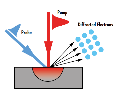
Figure 4: The diffraction intensity change observed in pump-probe spectroscopy directly relates to the non-equilibrium energy transport caused by ultrafast laser excitation
The diffraction intensity change caused by the ultrafast laser is governed by the Debye-Waller effect and is given by:
- I(t) is the diffraction intensity at time t
- I0 is the initial intensity
- T0 is the initial temperature
- u2 (T) is the atomic mean square displacement given by:
- ħ is the reduced Planck’s constant, or Planck’s constant divided by 2π
- m is the effective mass of the unit cell
- kB is Boltzmann’s constant
- θD is the Debye temperature
Equation 4 and Equation 5 display the change in the diffracted intensity following laser excitation at different pump-probe time delays. The diffraction intensity change will also be different whether the probe and pump beams are illuminating the coated surface of the optic or the coating-substrate interface (Figure 5). The system’s delay time for reaching equilibrium temperature after ultrafast excitation is much longer than the ultrafast pulse duration. The heating of the nanofilm takes place at a picosecond time scale and arises from the equilibration of the excited electron following ultrafast laser excitation.
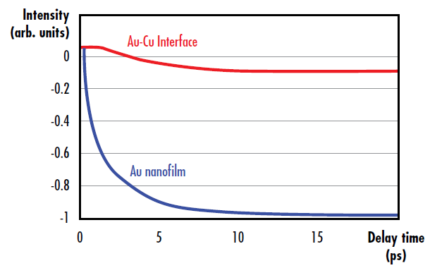
Figure 5: Diffraction intensity change due to electron-phonon and phonon-phonon scattering following ultrafast excitation in a gold nanofilm (blue), as well as diffraction intensity change at the gold-copper interface from energy transfer from the gold nanofilm to the copper substrate (red)
Highly-Dispersive Mirrors from Edmund Optics®
VIEW NOW
Webinar Recording: Ultrafast Optics: Challenges and Solutions
WATCH NOW
References
- Mao, S. S. et al., “Dynamics of Femtosecond Laser Interactions with Dielectrics.” Appl. Phys. A 2004, 79, 1695.
- Jiang, L., and H. l. Tsai. “Energy Transport and Material Removal in Wide Bandgap Materials by a Femtosecond Laser Pulse.” International Journal of Heat and Mass Transfer, vol. 48, no. 3-4, 2005, pp. 487–499., doi:10.1016/j.ijheatmasstransfer.2004.09.016.
- Wellershoff, Sebastian S., et al. “The Role of Electron–Phonon Coupling in Femtosecond Laser Damage of Metals.” Appl. Phys. A, vol. 69, Dec. 1999, pp. 99–107.
- Shin, Taeho, et al. “Extended Two-Temperature Model for Ultrafast Thermal Response of Band Gap Materials upon Impulsive Optical Excitation.” The Journal of Chemical Physics, vol. 143, no. 19, 2015.
- Karam, Tony E, et al. “Enhanced Photothermal Effects and Excited-State Dynamics of Plasmonic Size-Controlled Gold–Silver–Gold Core–Shell–Shell Nanoparticles.” J. Phys. Chem, vol. 119, 17 July 2015, pp. 18573–18580., doi: 10.1021/acs.jpcc.5b05110.
- Heilpern, Tal, et al. “Determination of Hot Carrier Energy Distributions from Inversion of Ultrafast Pump-Probe Reflectivity Measurements.” Nature Communications, vol. 9, no. 1, Oct. 2018, doi:10.1038/s41467-018-04289-3.
- Hu, Jianbo, et al. “Ultrafast Lattice Dynamics of Single Crystal and Polycrystalline Gold Nanofilms☆.” Chemical Physics Letters, vol. 683, 2017, pp. 258–261., doi:10.1016/j.cplett.2017.04.021.
- Gedik, Nuh. “Techniques.” Gedik Group, Massachusetts Institute of Technology, 2013, web.mit.edu/gediklab/research.html
More Resources
- Understanding and Specifying LIDT of Laser Components Application Note
- Laser Damage Threshold Testing Application Note
- Highly-Dispersive Ultrafast Mirrors for Dispersion Compensation Video
- Ultrafast Lasers – The Basic Principles of Ultrafast Coherence Application Note
- LIDT for Ultrafast Lasers Application Note
- Trending in Optics: Ultrafast Highly-Dispersive Mirrors
- Laser Damage Threshold Scaling Calculator
- Uncertainty in LIDT Specifications Application Note
- Different Types of LIDT Specifications Application Note
- Bulk Laser Damage in Glass Application Note
- Importance of Beam Diameter on Laser Damage Threshold Application Note
- LIDT for Ultrafast Lasers Application Note
- Why Laser Damage Testing is Critical for UV Laser Applications Application Note
- A Guide to (Not Over) Specifying Losses in Laser Optics Application Note
- Metrology at Edmund Optics: Measuring as a Key Component of Manufacturing Video
- Metrology for Laser Optics Application Note
- Key Parameters of a Laser System Application Note
- Laser Optics Lab Video Series


or view regional numbers
QUOTE TOOL
enter stock numbers to begin
Copyright 2023, Edmund Optics India Private Limited, #267, Greystone Building, Second Floor, 6th Cross Rd, Binnamangala, Stage 1, Indiranagar, Bengaluru, Karnataka, India 560038
California Consumer Privacy Acts (CCPA): Do Not Sell or Share My Personal Information
California Transparency in Supply Chains Act
This content may include material that has been generated or modified using artificial intelligence (AI).
The FUTURE Depends On Optics®