


Aberrational Balancing of MTF in Lens Design
Authors: Gregory Hollows, Nicholas James
This is Section 3.7 of the Imaging Resource Guide.
Designing individual custom lenses for each application is neither cost-effective nor practical. Instead, most lenses are designed for a large range of coverage so that they are both cost-effective and capable of meeting the needs of many applications. This adaptability does have faults; the most important of which is that it is not possible to simultaneously achieve maximum performance in all fields of view (FOVs), WDs, and sensors. These lenses can be considered “jack of all trades, master of none” and are the most common lenses on the market today. However, as resolutions continue to increase, other options may need to be explored to maximize system performance.
Aberrational Effects
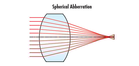
To maximize system performance, it is necessary to understand what can negatively affect an optical design. Aberrations, such as chromatic aberration, astigmatism, spherical aberration, and field curvature, must be reduced as much as possible to yield high image quality. Specific aberrations are discussed later in this section. Almost all these aberrations are directly related to the WD and magnification (ratio of the FOV to the sensor size) of the lens, although they may not necessarily be related to one another. When the WD or the sensor size and FOV change, aberrations are shifted, and lens performance changes. For instance, although maximum reduction of aberrations can be achieved by designing a lens for a single FOV and WD, small changes in the WD or magnification will cause a rapid decline in this ultra-high level of performance. This decrease will occur more rapidly the farther these lenses move from their optimized position.
In lenses that are designed for multiple applications, aberrations are balanced over a range of WDs and magnifications. Although these lenses cannot exceed the performance of lenses that have been designed for a specific WD and magnification, they can work well over larger defined ranges. However, as pixels continue to become smaller, the compromises inherent in a general-purpose range-balanced design is more pronounced.
Hybrid Approaches
Hybrid approaches to lens design have been developed for situations in which time and budget do not allow the design of a custom lens that is optimized for only a single WD and magnification. A hybrid approach involves a lens that has been designed so that the spacing between elements or groups of elements can be adjusted so that the design is slightly changed, and performance can be increased for a desired magnification and WD. For example, a lens design created for line-scan sensors may have a specific magnification associated with it, such as 0.33X (Figure 1). On a camera with a 60mm line scan array, this will yield a FOV of 180mm.
Figure 1: A lens design created for a line-scan sensor that has a set spacing for 0.33X.
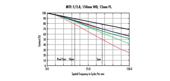
Lens performance can be analyzed by referencing its modulation transfer function (MTF) curve. MTF curves are described in Lens Performance Curves, The Modulation Transfer Function (MTF), and MTF curves and Lens Performance. Figure 2 shows the associated MTF curve of the lens in Figure 1 at 0.33X magnification. The curves displayed here are limited to 100$ \small{\tfrac{\text{lp}}{\text{mm}}} $, reflecting the resolution capabilities of a 12k line scan sensor with 5μm pixels. Two pixels are the smallest sampling area that can be used to distinguish the separation between information created by a lens. In this example, one line pair equals a total space of 10μm (two 5μm pixels); there are 100 sets of 10μm in 1mm, thus 100$ \small{\tfrac{\text{lp}}{\text{mm}}} $ is the limiting resolution of the camera.
Figure 2: MTF performance curves for the 0.33X lens at nominal magnification.
In Figures 3 and 4, the lens is refocused to obtain other FOVs, and the associated MTF curves for the 0.33X-optimized lens design are shown. At magnifications of 0.5X (120mm FOV) and 1.0X (60mm FOV) display lower levels of performance. To overcome this, the spacing between the lens elements can be adjusted to optimize the performance for different magnifications. Figure 5 shows the optical layout for the same lens system re-optimized for high magnification; note that the spacing between the lens elements marked in red is changed from Figure 1, to compensate for the FOV/WD change.
Figure 3: MTF performance curves for the 0.33X lens at 0.5X magnification (120mm FOV).
Figure 4: MTF performance curves for the 0.33X lens at 1.0X magnification (60mm FOV).
Figure 5: Adjusting the space between the lenses, marked in red, improves MTF for the lens at 1X magnification. Note the larger gap.
Figure 6 shows the MTF performance of the 1.0X-optimized lens at its design magnification. Notice the extreme difference in performance between Figures 6 and 4. Both lenses use the same glass elements and were designed simultaneously but making a spacing change results in a huge difference in performance. Figures 7 and 8 show the MTF of the 1.0X-optimized lens design at 0.5X and 0.33X respectively. Again, a rapid change in performance is the magnification is moved away from the nominal.
Figure 6: MTF performance curves for the 1.0X-optimized lens at its nominal magnification.
Figure 7: MTF performance curves for the 1.0X lens used at 0.5X magnification.
Figure 8: MTF performance curves for the 1.0X lens used at 0.33X magnification.
This hybrid approach allows for several applications to be solved more effectively because it yields better performance than a single lens designed to address multiple applications. Hybrid designs provide multiple achievable options to increase system performance. Because this is less complex than multiple custom lenses, off-the-shelf solutions are typically more available and less expensive than complete customs.
While a hybrid solution increases performance, it can be more expensive than standard lenses and can have additional issues. First, it will not likely achieve the full performance capability of a true custom solution that has been specifically designed for a single WD and magnification. As pixels become increasingly smaller, it can still be difficult for the optics in hybrid solutions to meet system requirements. Second, hybrid lenses will suffer rapid performance decline outside of their specified range, like narrowly designed lens solutions. Finally, since hybrid approaches result in several different lenses that each require specific materials, additional time is required to build the specific magnifications, and it may be necessary to use large, complicated mounting and focusing accessories to make the sensor/lens system operate as required.


or view regional numbers
QUOTE TOOL
enter stock numbers to begin
Copyright 2023, Edmund Optics India Private Limited, #267, Greystone Building, Second Floor, 6th Cross Rd, Binnamangala, Stage 1, Indiranagar, Bengaluru, Karnataka, India 560038
California Consumer Privacy Acts (CCPA): Do Not Sell or Share My Personal Information
California Transparency in Supply Chains Act
This content may include material that has been generated or modified using artificial intelligence (AI).
The FUTURE Depends On Optics®